Appearance
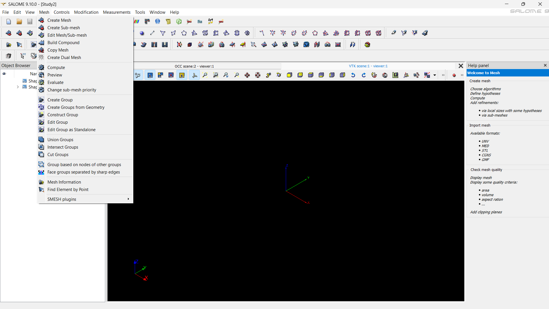
Creating Meshes
Once the geometry is ready, the next step is to generate a mesh — the discrete representation of your model that will be used in the finite element solver.
In this section, we’ll create a mesh for the same cantilever beam we built earlier using the Salome Mesh module.
Step-1: Switching to the Mesh Module
- Open your saved Salome project containing the beam geometry.
- From the module dropdown at the top, select Mesh. The interface will now switch to show the meshing tools and options.
Step-2: Creating a New Mesh
Click on Create Mesh from the toolbar or go to Mesh → Create Mesh.
In the dialog box that appears, select your beam geometry from the Main Shape list. You should see your geometry name appear in the selection field.
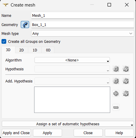
Now you’re ready to choose the mesh algorithm and define its parameters.
Step-3: Selecting the Type of Mesh
Salome supports several meshing algorithms, depending on whether you want to mesh edges, surfaces, or volumes. In our case, since the cantilever beam is a solid, we’ll use a 3D mesh.
In the 1D–2D–3D Meshing options, choose:
- 1D: Wire discretization – defines how edges are divided.
- 2D: Surface meshing – typically triangular elements for faces.
- 3D: Volume meshing – tetrahedral elements for solids.
By default, Salome will automatically handle these layers if you select a 3D algorithm.
Step-4: Defining Meshing Parameters
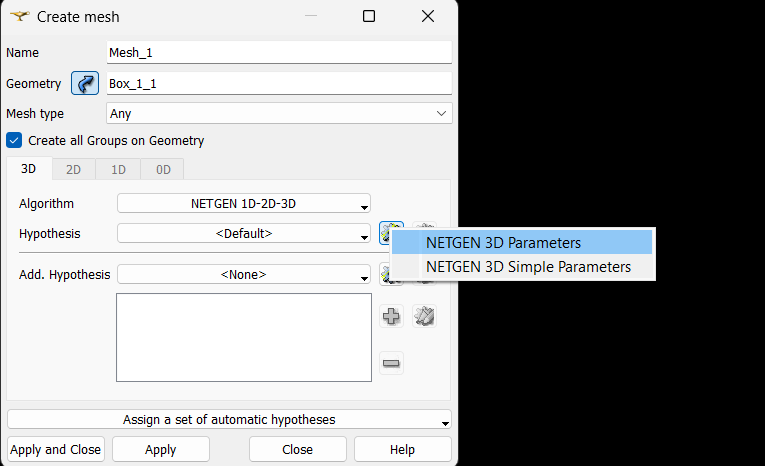
Once the geometry is selected and the meshing type is chosen, click on the gear icon ⚙️ next to the 3D meshing algorithm.
This opens the Hypothesis Construction, where you can control how fine or coarse the mesh should be.
Here you can specify:
- Minimum Element Size – the smallest possible element dimension in the mesh.
- Maximum Element Size – the largest element dimension allowed.
- Element Distribution Type – select Coarse, Medium, or Fine refinement depending on your study’s accuracy requirements.
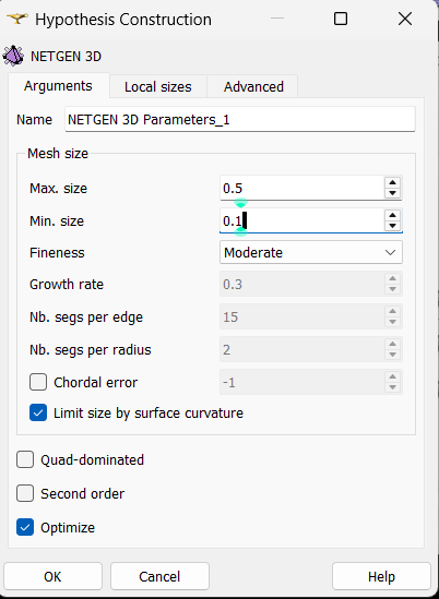
For this example, you can start with:
- Min size =
0.1 - Max size =
0.5 - Refinement = Moderate
You can leave other parameters as default for now.
Click Apply and Close when done.
Tip: Smaller element sizes result in higher accuracy but increase computational cost. Adjust based on your available resources and required precision.
Step-5: Adding Local Refinement (Optional)
If you want finer mesh elements in specific regions — such as near the fixed end of the beam or around the force application area — you can define local refinement using the Hypothesis Construction options.
In the Object Browser, right-click on your Mesh object and select Edit mesh.
Click the gear icon ⚙️ next to the local refinement option; a Hypothesis Construction pop-up will appear, similar to the above.
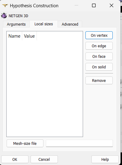
When the Hypothesis Construction window appears, switch to the Local Sizes tab. Here, you can define local mesh refinement settings under different categories such as:
- On vertex – refine elements around a specific point.
- On edge – refine along a line or edge.
- On face – refine a surface region (commonly used for load or boundary faces).
- On solid – apply local refinement inside a volume region.
You can enter the desired size value for each selection depending on the refinement needed.
Note: Ensure that the faces or regions where you plan to apply local refinement have already been defined as physical groups in the Salome-Shaper module during geometry creation. This makes it easier to identify and select them consistently during the meshing process.
Once the local refinements are defined, click OK to apply the settings. This targeted refinement helps achieve better accuracy in critical areas without over-meshing the entire model.
Step-6: Generating the Mesh
Once all parameters are set:
- Right-click on the mesh name in the Object Browser.
- Select Compute.
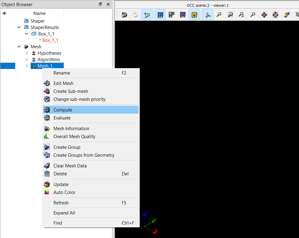
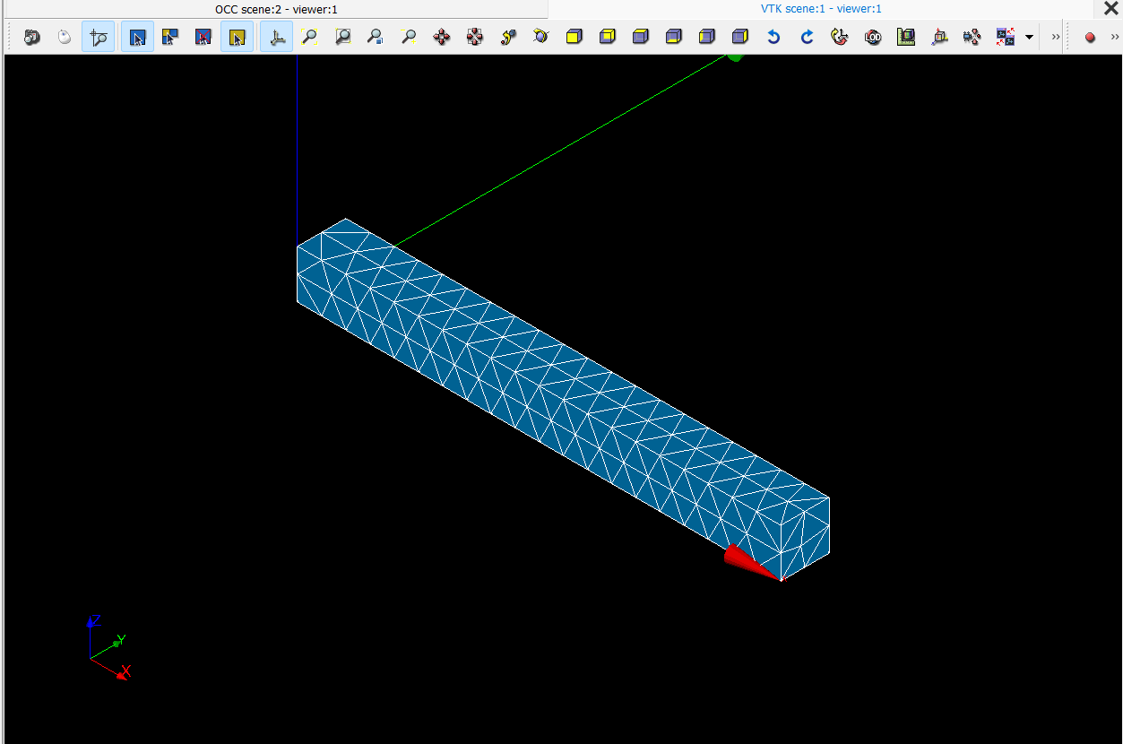
Salome will now generate the mesh based on your defined parameters and display it in the viewer.
You can visually inspect it by rotating and zooming around the geometry. If the mesh appears too coarse or too fine, simply modify the meshing parameters and recompute.
Step-7: Verifying the Mesh
After the mesh is generated, check:
- Element count and distribution (in Mesh → Information).
- Smoothness and uniformity near boundaries.
- Correct element connectivity and no open gaps.
A well-refined mesh should clearly capture geometry features while maintaining uniform element shapes.
Summary
You’ve now created a 3D finite element mesh for your cantilever beam using the Salome Mesh module. You learned how to:
- Select the geometry and meshing algorithm (1D–2D–3D)
- Define global mesh parameters (min/max size, refinement level)
- Optionally apply local refinements
- Generate and compute the final mesh
In the next section, we’ll cover how to export the mesh into formats like .med or .xdmf so it can be used directly in FEniCS for simulation.