Appearance
Creating Basic Geometries
To understand the geometry-building workflow in Salome, let’s start with a simple and practical example — creating a cantilever beam. This example will walk you through the process of building a basic 3D geometry, assigning its dimensions, and defining physical groups that will later be used in FEniCS simulations for applying boundary and loading conditions.
Step-1: Creating a New Geometry in Shaper
Launch Salome and select the Shaper module from the dropdown menu at the top.
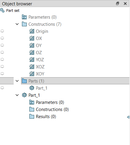
By default, you should see a
Part_1listed in the Object Browser. If not, create a new part by clicking New Part in the toolbar or through Part → Create Part.A new part (e.g.,
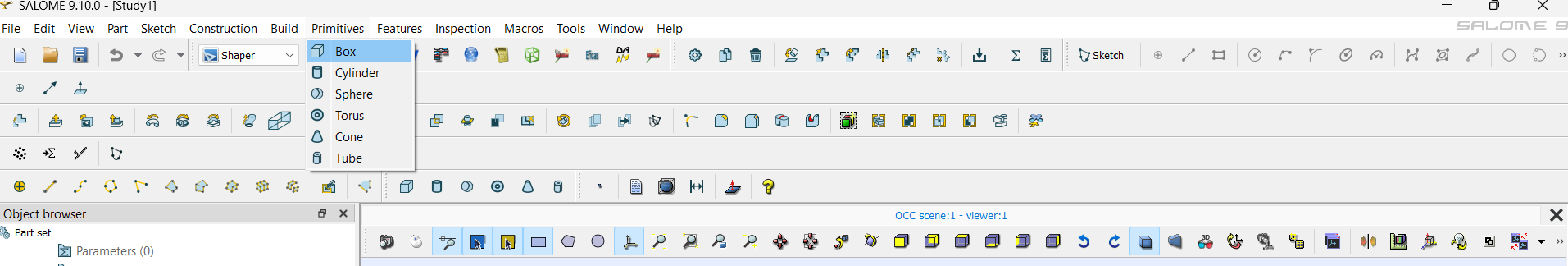
Part_1) will appear in the Object Browser.Inside this part, click Create Box from the Primitives section on the toolbar.
Step-2: Defining the Dimensions of the Beam
The Box primitive is one of the simplest ways to create a 3D solid.
 For a cantilever beam, let’s assume the following dimensions (in meters):
- Length (X-direction) = 1.0 m
- Height (Y-direction) = 0.1 m
- Width (Z-direction) = 0.1 m
In the Box dialog:
- Set X Length =
1.0, Y Length =0.1, and Z Length =0.1. - Keep the position origin
(0, 0, 0)as the default, unless you want to offset the geometry. - Click Apply and Close.
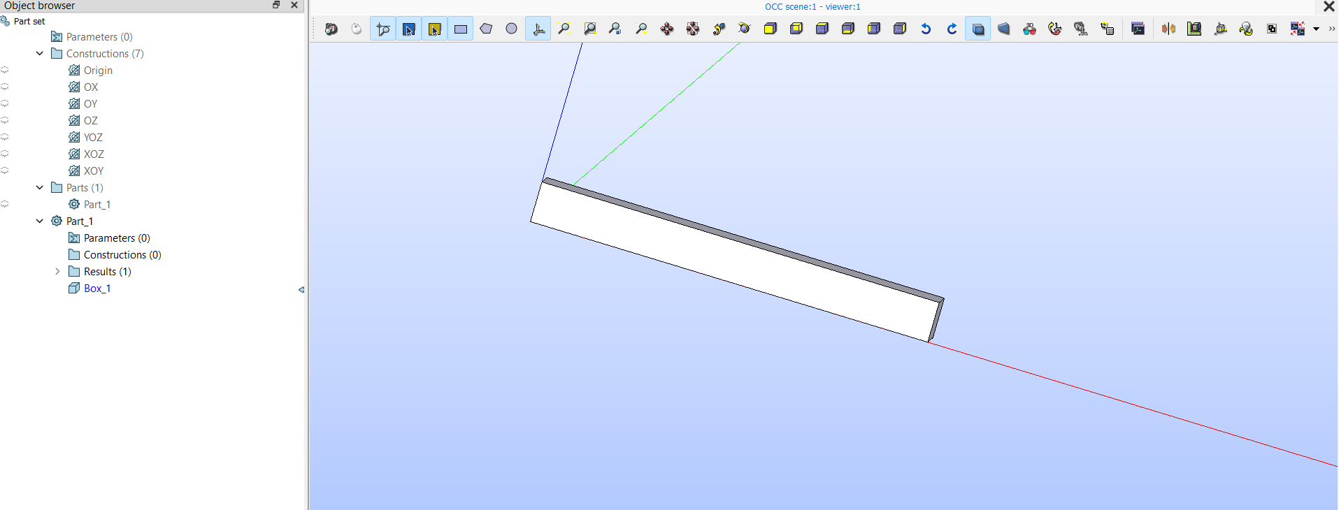
You should now see a rectangular block representing the cantilever beam in the 3D viewer.
Tip: To move (pan) the view, hold the
Ctrlkey and the right mouse button while dragging. Zoom in or out by holding theCtrlkey and dragging with the left mouse button. This helps you view the geometry from different angles.
Step-3: Verifying the Geometry (Optional)
Before proceeding, it’s a good practice to verify the geometry:
- Use the Inspection tab to check the volume and bounding box dimensions.
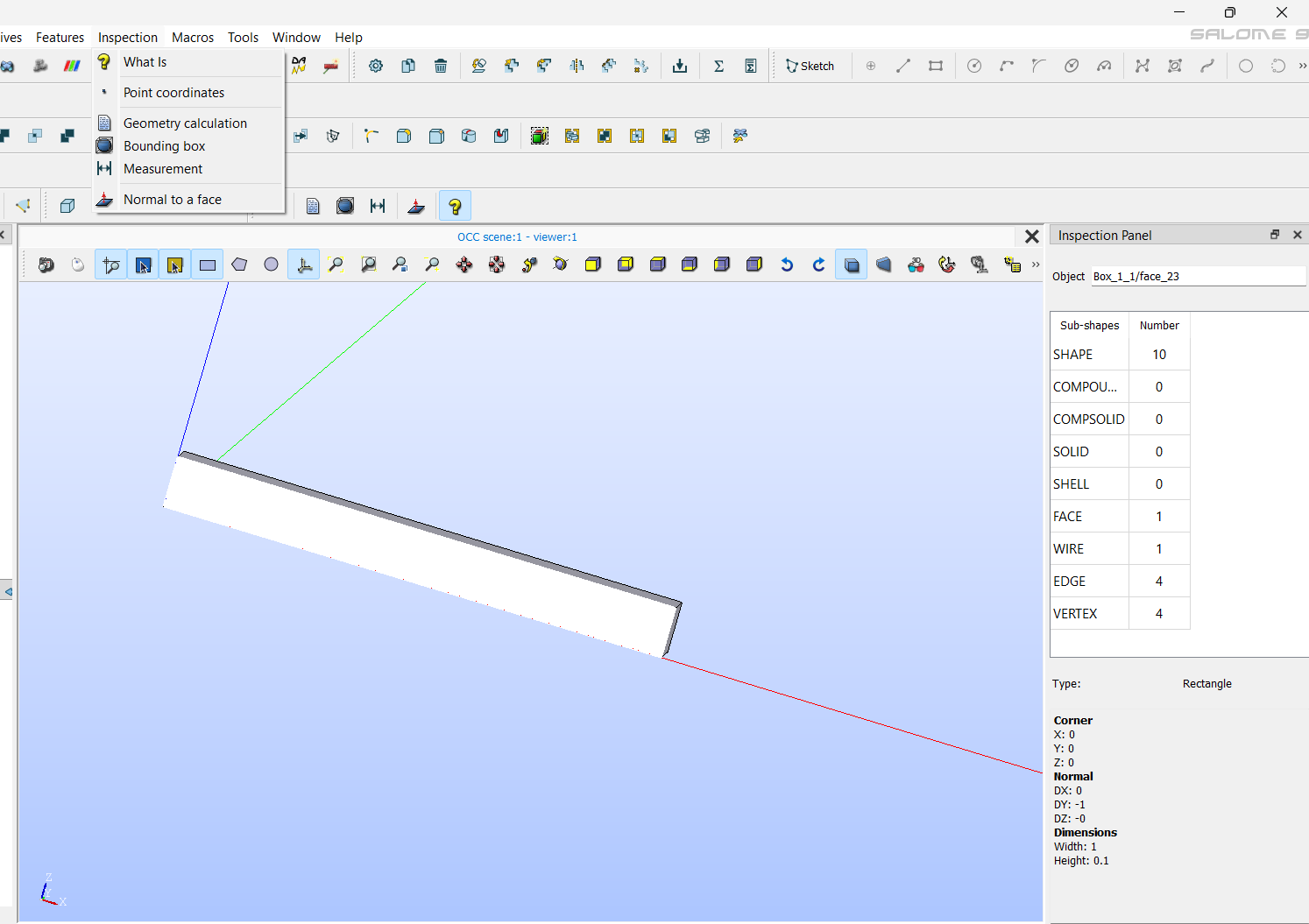
Once verified, you have a valid beam geometry ready for meshing and simulation.
Step-4: Understanding Physical Groups
When we export the geometry for simulation in FEniCS, we need to identify specific regions or surfaces of the model — such as where the boundary conditions or loads will be applied. This is done through Physical Groups in Salome, which correspond to markers in FEniCS.
These groups help distinguish:
- Different boundary conditions (e.g., fixed or loaded faces)
- Distinct material regions (in multi-material models)
- Volume domains for assigning specific properties
Step-5: Assigning Physical Groups
Once your geometry is complete and all construction operations (like Boolean cuts, fillets, or transformations) are done, you can assign the physical groups.
Note: This step should always be done at the end, because applying further operations afterward can alter the topology and invalidate the assigned groups.
For the cantilever beam
In the top menu bar, go to Features → Group.
A Group dialog box will appear.
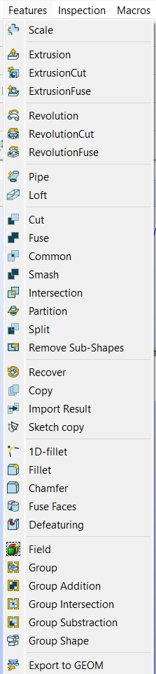
In the dialog box, you’ll see four buttons at the top for different selection types — point, edge, surface, and volume. Choose the surface icon (the third one).
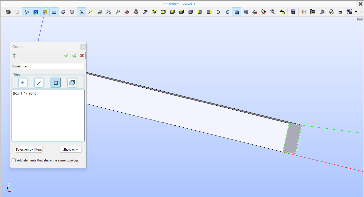
Click inside the selection panel below, then move your cursor over the beam in the viewer and select the face where you want to apply the force boundary (the free end of the beam).
In the Name field, type
forced.To add another group, click on the “✓+” arrow button next to the name field. Repeat the same process for the fixed and material_1 groups:
- For
fixed→ select the opposite face (the fixed end of the beam). - For
material_1→ switch the selection type from surface to volume (the fourth icon), and select the entire solid volume of the beam.
- For
Once all groups are defined, click the check mark (✓) button to confirm and close the dialog.
This way, the physical groups — fixed, forced, and material_1 — are successfully assigned. These will later act as boundary and material identifiers in the FEniCS simulation.
These names will appear under your geometry’s tree in the Object Browser, under the Groups section.
Step-6: Why Physical Groups Are Important
When you export the geometry to .med or .xdmf format, these physical groups will automatically carry unique region IDs. In FEniCS, these IDs can then be accessed using MeshFunction or MeshValueCollection to apply:
- Dirichlet boundary conditions (fixed surfaces)
- Neumann or traction loads (force boundaries)
- Material properties (volumetric domains)
This structured approach ensures that your simulation setup directly matches the physical intent of the geometry.
Step-7: Save Your Work
After defining all groups:
- Save your study using File → Save As.
- When saving, select the appropriate folder and always use a lowercase, alphanumeric file name without spaces. If needed, use underscores (
_) to separate words.
Example:cantilever_beam_v1.med
Once you have covered these steps, you have successfully created a basic 3D geometry in Salome and now you can try the following tutorial videos for creating different geometries from this playlist -
Playlist: Salome Geometry Tutorials
Summary
You’ve now created your first 3D geometry — a simple cantilever beam — using the Shaper module in Salome. You learned how to:
- Build a geometry using the Box primitive
- Define exact dimensions
- Assign physical groups for boundary and material identification
Remember, physical groups should always be created at the final stage, after all operations are completed. This ensures that their face and volume markers remain consistent during conversion for FEniCS simulations.
In the next sections, we will cover how to apply different Boolean operations, generate meshes, and explore other key aspects of working with geometries in Salome.