Generalized Phase-Field Models for Fracture Nucleation
Learning objectives
By the end of this lesson, you should be able to:
- Explain why classical phase-field fracture is not always sufficient for fracture nucleation.
- Understand what makes a phase-field model "generalized."
- Describe the role of strength surfaces in generalized nucleation models.
- Distinguish between classical variational, complete nucleation, and hybrid cohesive-zone phase-field approaches.
- Understand why independent control of strength and toughness matters.
- Explain the conceptual contribution of Kumar, Bourdin, Francfort, and Lopez-Pamies.
- Recognize the modeling tradeoff between variational consistency, correct nucleation strength, and correct propagation toughness.
1. What does "generalized" mean here?
A generalized phase-field fracture model tries to extend the classical model so that it can represent both:
- Crack propagation from existing cracks
- Crack nucleation from uncracked or nearly uncracked regions
To do this, the model should include three independent material ingredients:
where:
- \(W(\varepsilon)\) is the elastic stored-energy function,
- \(G_c\) is fracture toughness or fracture energy,
- \(F(\sigma)=0\) is the strength surface.
The goal is not merely to make damage appear.
The goal is to make damage appear at the correct stress state and then propagate with the correct fracture energy.
2. Three major phase-field approaches incorporating strength
Recent literature often distinguishes three broad approaches to incorporating strength into phase-field fracture:
- Classical variational phase-field approach
- Complete nucleation approach
- Hybrid cohesive-zone phase-field approach
A 2025 comparison by Khayaz, Dahal, and Kumar describes these as three main approaches trying to reconcile strength and toughness; it notes that classical variational models preserve the variational structure but do not accurately incorporate arbitrary strength surfaces, while complete nucleation precisely accounts for the strength surface.
We discuss each below.
3. Approach 1: classical variational phase-field model
The classical model minimizes an energy of the form
where
for AT2.
The main advantage is that the model is strongly variational.
The displacement and damage fields come from energy minimization.
The main limitation is that the model does not generally encode an arbitrary strength surface.
Its apparent nucleation behavior is controlled indirectly by:
- \(G_c\),
- \(\ell\),
- elastic moduli,
- degradation function,
- crack density function,
- energy split.
4. Classical variational model: advantages and limitations
Advantages
- Closely connected to Griffith fracture.
- Variationally elegant.
- Well suited for crack propagation.
- Handles branching and merging naturally.
- Relatively straightforward to implement in FEM.
Limitations
- Nucleation stress is not generally an independent input.
- Arbitrary strength surfaces are hard to prescribe.
- \(\ell\) may influence apparent strength.
- Uniform-stress nucleation may not match experiments.
- Different tension-compression splits can alter nucleation.
The key point is:
Classical phase-field models can produce damage nucleation, but they do not generally model material strength as an independent constitutive property.
5. Approach 2: complete nucleation phase-field model
The complete nucleation approach aims to incorporate strength directly.
Its goal is to satisfy two conditions:
Correct nucleation
For an uncracked or nearly uncracked body, fracture should nucleate when
Correct propagation
For large pre-existing cracks, propagation should remain governed by
Kumar, Bourdin, Francfort, and Lopez-Pamies proposed a modified phase-field theory with this motivation: model nucleation from large cracks, small cracks, smooth and non-smooth boundary points, and the bulk, while preserving the standard model's crack-propagation capability.
This is why the approach is sometimes described as a complete nucleation theory.
6. Complete nucleation: conceptual structure
The complete nucleation model modifies the crack-driving force.
Classical phase-field models often use a crack-driving quantity related to elastic energy:
The complete nucleation idea is to use a driving force that is aware of the material strength surface:
The exact mathematical form depends on the specific strength surface and formulation.
Conceptually, it is designed so that:
for uniform or local stress states.
At the same time, the model should preserve Griffith-type propagation for existing cracks.
7. Complete nucleation is not just a stress criterion
It is tempting to think:
Just add a stress criterion to the phase-field equation.
But this is not enough.
A correct model must avoid breaking the propagation behavior.
If the driving force is changed carelessly, the model may nucleate at the right strength but propagate with the wrong effective toughness.
Therefore, the complete nucleation model must balance:
- local strength-controlled initiation,
- nonlocal phase-field regularization,
- toughness-controlled crack growth,
- irreversibility,
- multiaxial stress-state dependence.
This is why the construction is more subtle than simply adding \(F(\sigma)\) to the damage equation.
8. Approach 3: hybrid cohesive-zone phase-field model
Hybrid cohesive-zone phase-field models use ideas from cohesive fracture.
In a cohesive-zone model, the traction-separation relation controls fracture.
A typical cohesive law has:
- peak traction,
- softening branch,
- critical separation,
- area under the curve.
The peak traction represents strength.
The area under the curve represents fracture energy.
A sketch is:
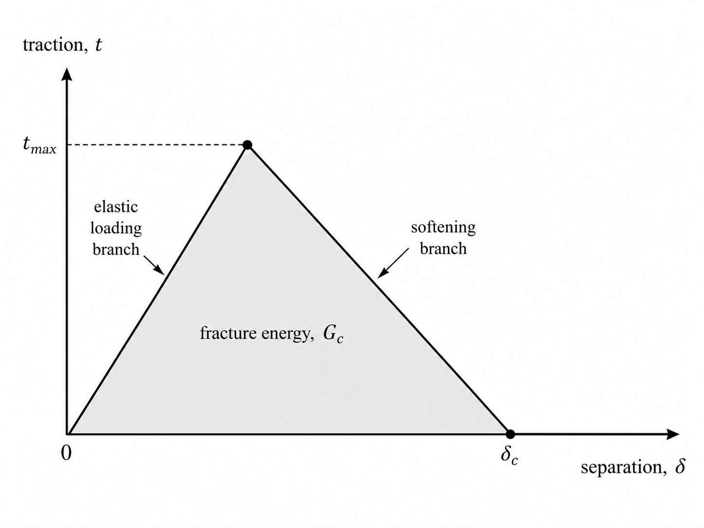
The area under this curve is related to
The peak is related to
Hybrid cohesive-zone phase-field models try to embed this type of strength control into a phase-field formulation.
9. Hybrid cohesive-zone model: strengths and risks
Strengths
- Can introduce a more direct strength parameter.
- Can mimic cohesive-zone softening behavior.
- Can improve control over damage onset.
- Often intuitive for engineers familiar with traction-separation laws.
Risks
- The model may sacrifice variational consistency.
- The crack driving force may be modified in a way that changes effective toughness.
- Mixed-mode propagation may become unreliable if the formulation is not carefully constructed.
- Calibration can be more complicated.
Recent comparative work reports that hybrid cohesive-zone modifications can incorporate strength but may cause crack propagation at an incorrect fracture toughness in some mixed-mode settings.
10. Comparison of the three approaches
| Feature | Classical variational | Complete nucleation | Hybrid cohesive-zone |
|---|---|---|---|
| Griffith propagation | Strong | Designed to preserve | May be affected |
| Variational structure | Strong | Modified/generalized | Often partly sacrificed |
| Independent strength surface | Limited | Yes | Partly/depending on model |
| Uniform-stress nucleation | Not general | Designed to match | Often improved |
| Arbitrary multiaxial strength | Difficult | Main goal | Model-dependent |
| Implementation difficulty | Moderate | Higher | Moderate to high |
| Calibration | \(G_c,\ell\), split | \(G_c,\ell,F(\sigma)\) | \(G_c,\ell,\sigma_c\), cohesive law |
| Risk | wrong nucleation | more complex formulation | wrong propagation toughness |
11. Why variational consistency is not the only goal
The classical variational model is elegant because everything comes from one energy functional.
However, if the model cannot represent an experimentally observed strength surface, then variational consistency alone is not enough.
A generalized model may sacrifice some strict variational structure to represent the physics of nucleation more accurately.
This creates a tradeoff:
Classical variational model:
    strong energy structure
    weaker general nucleation control

Complete nucleation model:
    explicit strength control
    modified/generalized structure

Hybrid cohesive-zone model:
    intuitive strength parameter
    possible propagation-toughness issues
The best choice depends on the problem.
12. Nucleation from large cracks, small cracks, boundaries, and bulk
A generalized nucleation model should ideally handle multiple regimes.
Large pre-existing cracks
For large cracks, the model should recover Griffith propagation:
Small cracks
For small cracks, strength and toughness both matter.
The model should transition smoothly between nucleation and propagation behavior.
Smooth boundaries
Cracks may nucleate at smooth boundaries when the local stress reaches the strength surface.
Non-smooth boundaries
Corners and notches create stress concentrations.
Nucleation may occur there earlier than in the bulk.
Bulk nucleation
Cracks may nucleate inside the material when
This is one of the most important tests for a generalized model.
13. Generalized crack-driving force
The damage equation in classical AT2 fracture often has the form
where \(\mathcal{H}\) is a history field based on tensile elastic energy.
A generalized model replaces or modifies \(\mathcal{H}\):
so that the damage equation becomes schematically:
The generalized driving force \(\mathcal{D}\) should activate damage when the stress state reaches the strength surface.
14. The role of stress in generalized models
In classical phase-field fracture, the crack-driving force is usually based on elastic strain energy.
In generalized nucleation models, the driving force may depend explicitly on stress:
or on stress invariants:
or on principal stresses:
This is necessary because strength surfaces are usually defined in stress space, not energy space.
For example, a maximum-principal-stress surface uses
A Drucker-Prager surface uses
and
A Mohr-Coulomb surface uses combinations of normal and shear stress.
15. General strength surface notation
Let the material strength surface be written as
A generalized phase-field model should satisfy:
This is analogous to plasticity yield surfaces, where the stress state is constrained by a yield function.
However, fracture is not plasticity.
Fracture creates new surfaces and must still account for toughness.
16. Analogy with plasticity
Strength surfaces in fracture are conceptually similar to yield surfaces in plasticity.
Plasticity uses a yield function:
Fracture nucleation uses a strength function:
Both define admissible stress states.
However, there is a key difference.
In plasticity, crossing the yield surface creates irreversible plastic strain.
In fracture, reaching the strength surface creates damage and eventually crack surfaces.
Fracture also requires the energetic cost:
or its phase-field approximation.
So fracture needs both:
and
17. Generalized model requirements
A good generalized phase-field nucleation model should satisfy the following requirements.
Requirement 1: correct elasticity
Before damage, the body should behave according to the specified elastic law:
Requirement 2: correct strength
In uniform stress or smooth nucleation tests, the model should nucleate when:
Requirement 3: correct toughness
For large cracks, the model should propagate cracks according to:
Requirement 4: irreversibility
Damage should not heal:
or
Requirement 5: mesh-objective behavior
The model should converge as the mesh is refined, provided the length scale is resolved.
Requirement 6: multiaxial robustness
The model should work under:
- tension,
- compression,
- shear,
- mixed-mode loading,
- multiaxial stress states.
18. Complete nucleation versus classical nucleation scaling
Classical phase-field apparent strength often scales as
Complete nucleation instead aims to prescribe strength independently:
For simple uniaxial tension, this may mean:
regardless of the chosen \(G_c\), as long as the model is properly calibrated and the length scale is resolved.
This does not mean \(\ell\) is irrelevant.
It means \(\ell\) should not accidentally determine the material strength when strength is supposed to be a separate input.
19. Mixed-mode fracture and strength surfaces
Mixed-mode fracture is especially important for generalized models.
In Mode I, the crack opens.
In Mode II, the crack slides.
In Mode III, the crack tears out of plane.
Classical Griffith-type propagation can work well for large cracks under many conditions.
But nucleation under mixed-mode or multiaxial loading requires a strength surface.
For example, a material may have different resistance under:
- pure tension,
- pure shear,
- combined tension-shear,
- compression-shear,
- triaxial tension.
A strength surface can encode these differences.
Recent comparisons of strength-incorporating phase-field models specifically examine mixed-mode loading because it is a demanding test of whether a model predicts both nucleation and propagation correctly.
20. Pressure-sensitive generalized models
Many materials are pressure-sensitive.
Examples include:
- rocks,
- concrete,
- ceramics,
- geomaterials,
- some polymers,
- ice and glacier materials in certain regimes.
Pressure-sensitive strength means that the material's failure behavior depends on hydrostatic stress:
A pressure-sensitive strength surface may look like:
If hydrostatic compression increases resistance, the model should predict delayed nucleation under compression.
If hydrostatic tension promotes cracking, the model should predict earlier nucleation under tensile pressure states.
Generalized phase-field models can, in principle, incorporate such surfaces.
21. Mohr-Coulomb, Mogi-Coulomb, and Hoek-Brown surfaces
More advanced generalized phase-field fracture models can incorporate classical failure surfaces from rock and geomaterial mechanics.
Examples include:
Mohr-Coulomb
Often used for frictional materials.
Mogi-Coulomb
Designed to improve failure prediction under true triaxial stress states.
Hoek-Brown
Often used for rock masses.
A 2026 paper by Chockalingam, Buganza Tepole, and Kumar describes phase-field fracture incorporating Mohr-Coulomb, Mogi-Coulomb, and Hoek-Brown strength surfaces, building on the Kumar et al. 2020 blueprint for incorporating strength surfaces while preserving toughness-controlled propagation.
22. Implementation-level view
In a finite element code, a generalized nucleation model usually requires additional constitutive calculations.
At each quadrature point, one may compute:
- Strain:
- Stress:
- Strength-surface value:
- Generalized crack-driving force:
- Damage evolution residual:
The damage equation may look schematically like:
The exact signs and coefficients depend on the chosen formulation.
23. Pseudocode for a generalized staggered algorithm
A generalized staggered algorithm may look like:
Given d_{n-1}, history variables, material parameters

For load step n:

    1. Apply load increment.

    2. Initialize d_n = d_{n-1}.

    3. Repeat until convergence:

        a. Solve mechanical equilibrium:

              div(sigma) + b = 0

        b. At quadrature points, compute:

              strain epsilon
              stress sigma
              strength surface F(sigma)
              generalized driving force D(sigma,F)

        c. Update history or irreversibility variables.

        d. Solve generalized damage equation.

        e. Enforce damage bounds:

              d_n >= d_{n-1}
              d_n <= 1

    4. Save fields:

              displacement u
              damage d
              stress sigma
              strength indicator F(sigma)
              reaction force
              energies
This is similar to a classical staggered phase-field solver, but with additional strength-surface calculations.
24. What to output for debugging
When implementing generalized nucleation models, it is useful to output more than just displacement and damage.
Useful fields include:
| Field | Why it is useful |
|---|---|
| \(d\) | Shows crack/damage location |
| \(\sigma_{\max}\) | Maximum principal stress |
| \(F(\sigma)\) | Shows where strength surface is reached |
| \(\mathcal{D}\) | Shows crack-driving force |
| \(\psi_e^+\) | Shows tensile energy |
| \(G_c\gamma_\ell\) | Shows fracture energy density |
| reaction force | Needed for load-displacement curves |
| total energy | Checks energetic consistency |
| active set | Shows where damage bounds are active |
A very useful diagnostic is:
Plot F(sigma) before damage nucleates.
If nucleation occurs far away from where \(F(\sigma)\) is largest, the implementation may be wrong.
25. Common implementation difficulties
Non-smooth strength surfaces
Some strength surfaces have corners.
Examples include:
- Mohr-Coulomb,
- Rankine-type criteria,
- piecewise surfaces.
Non-smoothness can cause Newton solver difficulties.
Principal stress derivatives
If the model depends on principal stresses, derivatives can be complicated when eigenvalues coincide.
Pressure sensitivity
Care must be taken with sign conventions.
In some communities, compression is positive.
In others, tension is positive.
Coupling with degradation
The stress used in the strength surface must be chosen carefully.
Should it be the undamaged stress?
The degraded stress?
An effective stress?
The answer depends on the formulation.
Irreversibility
Strength-controlled nucleation must still obey:
26. Effective stress versus degraded stress
A subtle issue is which stress enters the strength surface.
In damaged material, the degraded stress may be
where \(\sigma_0\) is the undamaged elastic stress.
If \(d\) grows, \(\sigma\) decreases because the material loses stiffness.
But if the strength surface uses the degraded stress, damage may reduce the stress and artificially make the material look safe again.
Therefore, some formulations use an effective or undamaged stress measure to evaluate nucleation.
This is conceptually similar to damage mechanics, where the effective stress represents the stress carried by the intact material skeleton.
The exact choice should follow the specific generalized model.
27. Generalized models and your glacier/fracture context
For your work, generalized nucleation concepts are useful when fracture does not simply grow from a prescribed notch.
They matter for problems like:
- crevasse nucleation from smooth glacier surfaces,
- crack initiation from stress concentration zones,
- hydrofracture initiation under water pressure,
- mixed-mode crevasse growth,
- pressure-dependent damage in ice,
- nucleation in no-notch simulations,
- fracture under compressive/shear stress states.
If your simulations include a large pre-existing notch, Griffith-type propagation may dominate.
If your simulations show cracks appearing in previously smooth regions, nucleation modeling becomes much more important.
28. How this relates to no-notch versus notched simulations
In a notched simulation, the crack path may be strongly influenced by the existing notch.
The problem is closer to propagation:
In a no-notch simulation, the model must decide where the first crack appears.
That is a nucleation problem:
If a classical phase-field model predicts different no-notch crack patterns under different rheologies or loading regimes, one question to ask is:
Are those patterns physically meaningful nucleation predictions, or are they influenced by the phase-field length scale, energy split, mesh, or artificial damage initiation behavior?
Generalized nucleation models help frame this question more rigorously.
29. Choosing between model classes
Use a classical variational phase-field model when:
- a large pre-existing crack is present,
- propagation is the main interest,
- Griffith toughness is the main material input,
- nucleation stress is not the central quantity.
Use a generalized or complete nucleation model when:
- cracks nucleate from smooth regions,
- multiaxial strength matters,
- tensile/compressive/shear strengths are known,
- pressure sensitivity matters,
- strength and toughness must be independently calibrated.
Use a cohesive-zone phase-field model when:
- traction-separation behavior is experimentally known,
- peak strength and softening are important,
- cohesive fracture interpretation is desired.
30. Conceptual summary
Classical phase-field fracture regularizes Griffith fracture:
It is excellent for crack propagation.
However, fracture nucleation often requires a strength surface:
Generalized phase-field fracture models try to include both:
and
The complete nucleation approach of Kumar and collaborators is important because it explicitly identifies strength as a missing ingredient in classical phase-field nucleation and proposes a way to incorporate it while preserving propagation behavior.
The core message is:
A fracture model should know not only how expensive it is to grow a crack, but also when a crack is allowed to appear.
31. Key terms
| Term | Meaning |
|---|---|
| Generalized phase-field model | Phase-field model extended to include additional fracture physics such as strength-controlled nucleation |
| Classical variational phase-field | Energy-minimizing Griffith-based phase-field model |
| Complete nucleation | Approach designed to capture nucleation from cracks, boundaries, and bulk while preserving propagation |
| Hybrid cohesive-zone phase-field | Phase-field model inspired by traction-separation cohesive laws |
| Strength surface | Surface in stress space defining fracture initiation |
| Toughness | Energy resistance to crack propagation |
| Apparent strength | Nucleation strength indirectly predicted by a model |
| Crack-driving force | Quantity that drives damage evolution |
| Effective stress | Stress measure used to evaluate material failure in damaged media |
| Mixed-mode fracture | Fracture involving combinations of opening, sliding, and tearing |
32. Suggested references
-
Griffith, A. A. (1921). The phenomena of rupture and flow in solids. Philosophical Transactions of the Royal Society of London. Series A.
-
Francfort, G. A., & Marigo, J.-J. (1998). Revisiting brittle fracture as an energy minimization problem. Journal of the Mechanics and Physics of Solids.
-
Bourdin, B., Francfort, G. A., & Marigo, J.-J. (2000). Numerical experiments in revisited brittle fracture. Journal of the Mechanics and Physics of Solids.
-
Kumar, A., Bourdin, B., Francfort, G. A., & Lopez-Pamies, O. (2020). Revisiting nucleation in the phase-field approach to brittle fracture. Journal of the Mechanics and Physics of Solids.
-
Kumar, A., Ravi-Chandar, K., & Lopez-Pamies, O. (2022). The revisited phase-field approach to brittle fracture: application to indentation and notch problems. International Journal of Fracture.
-
Khayaz, U., Dahal, A., & Kumar, A. (2025). A comparison of phase field models of brittle fracture incorporating strength: I — Mixed-mode loading.
-
Chockalingam, S., Buganza Tepole, A., & Kumar, A. (2026). The phase-field model of fracture incorporating Mohr-Coulomb, Mogi-Coulomb, and Hoek-Brown strength surfaces.
-
Lopez-Pamies, O., & Bourdin, B. (2022). Phase-field approaches to fracture in the 3rd millennium. International Journal of Fracture.
-
Drucker, D. C., & Prager, W. (1952). Soil mechanics and plastic analysis or limit design. Quarterly of Applied Mathematics.
-
Anderson, T. L. (2017). Fracture Mechanics: Fundamentals and Applications. CRC Press.
Generalized brittle fracture models improve nucleation behavior. The next extension is different: ductile fracture, where plasticity and fracture evolve together.